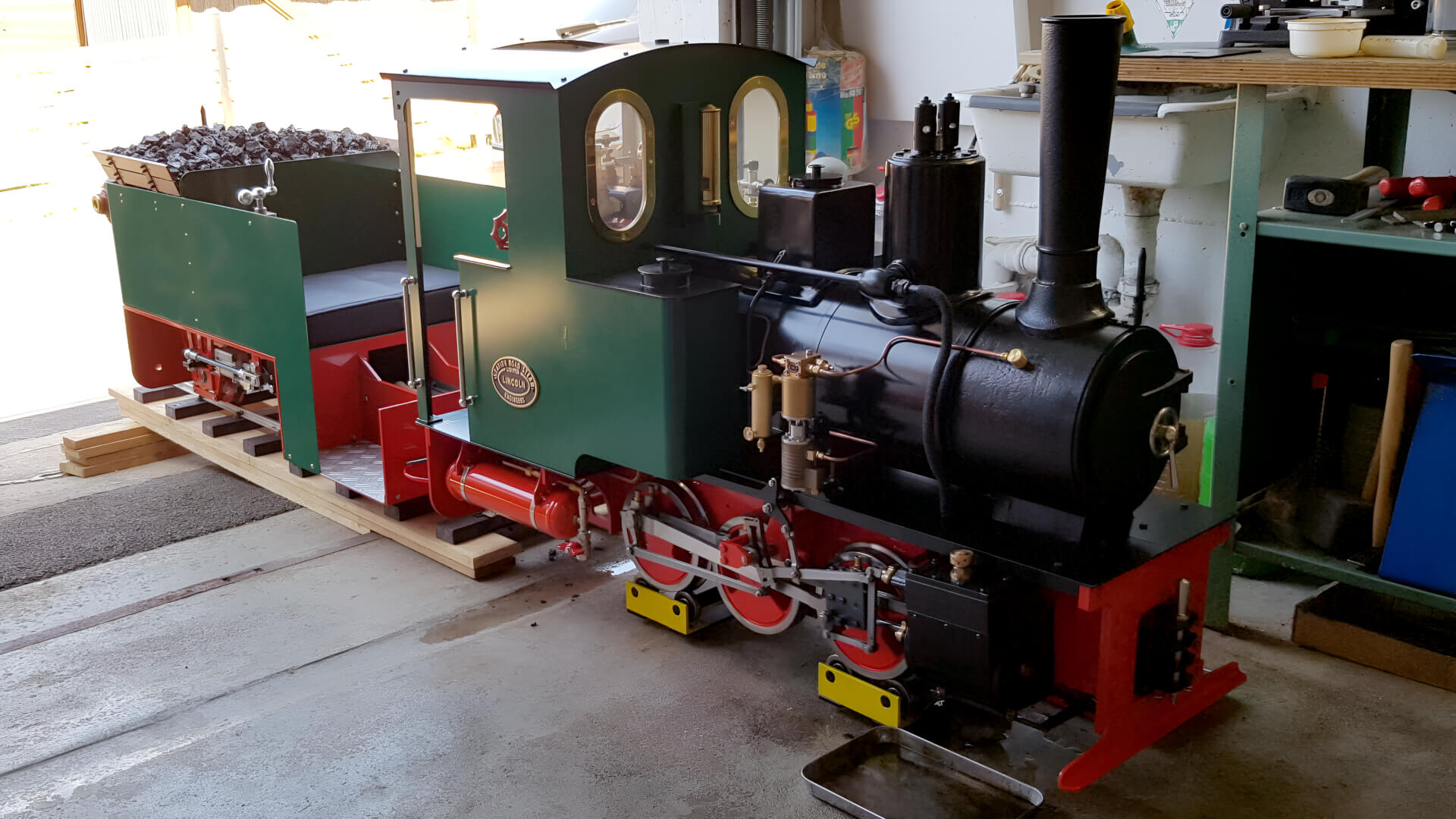
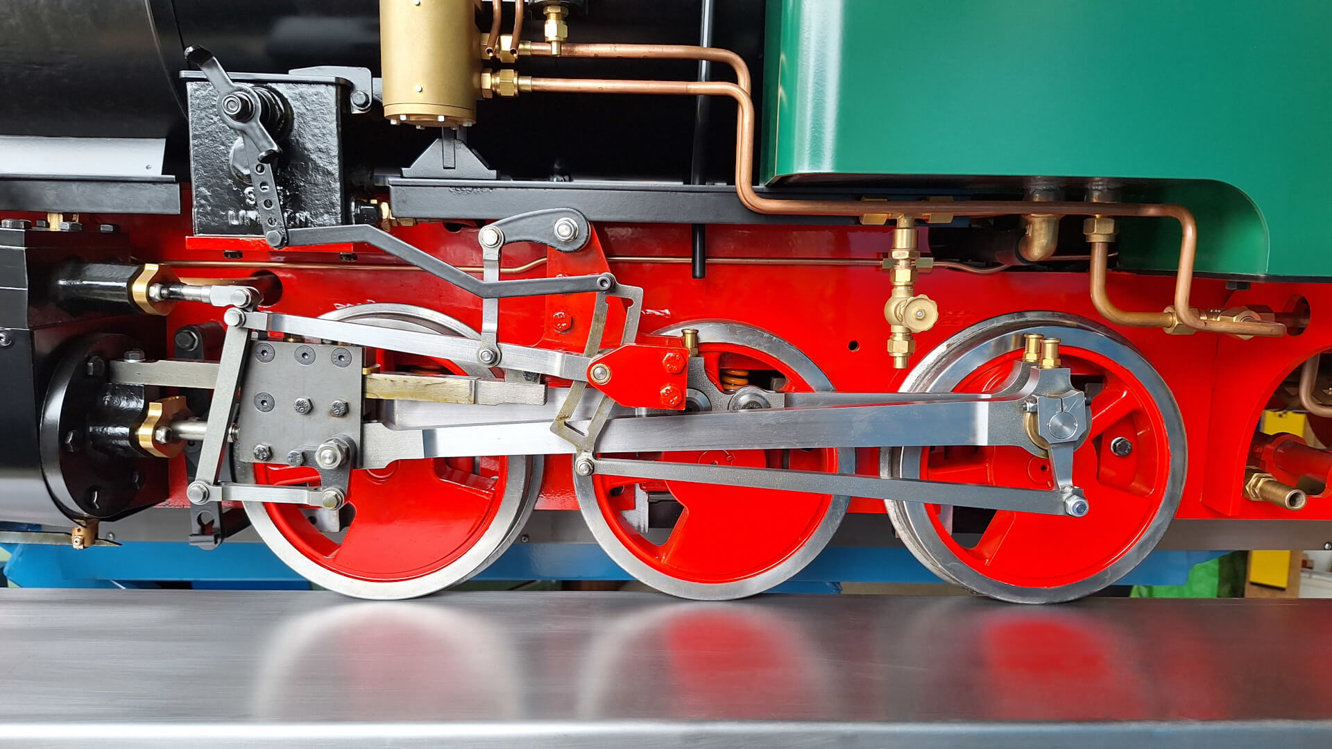
Built by Station Road Steam in 2020/2021 as 7 ¼″ gauge Feldbahn 0‑6‑0T (1426) in standard livery with brass spectacles, rims left in bright machine finish and fitted with a single note whistle (Type 28).
Pre-delivery video showing the steam test on YouTube: 7 1/4 inch gauge Feldbahn 0‑6‑0 .
Modifications
Derailing Bar
A little feature that is supposed to prevent major damage when unintentionally leaving the tracks. See project Derailing Bar for more.
Rear Plate
The rear plate was fitted with angle-push-in fittings to take water and pressurised air. It was also painted completely red (instead of the factory-supplied black/red livery).
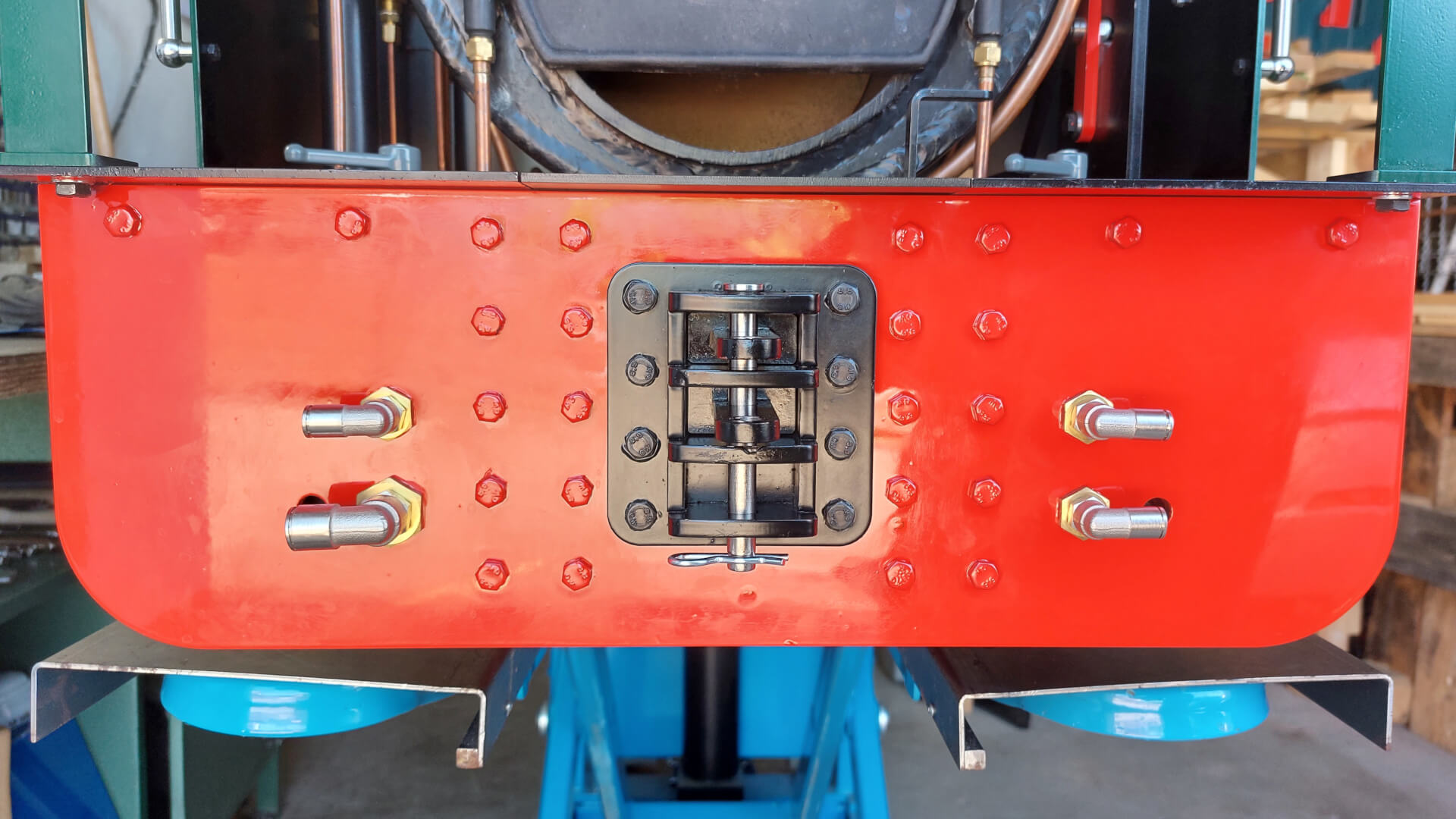
Stock components used (and visible in the photo):
- 3x Bulkhead Screw Connections G ⅛" (SV 18 MS)
- 3x Angle Push In Fittings G ⅛" for 6 mm pipes (IQSL 186 G MSV)
- 1x Bulkhead Screw Connection G ¼" (SV 14 MS)
- 1x Angle Push In Fitting G ¼" for 10 mm pipes (IQSL 1410 G MSV)
Feed Pump
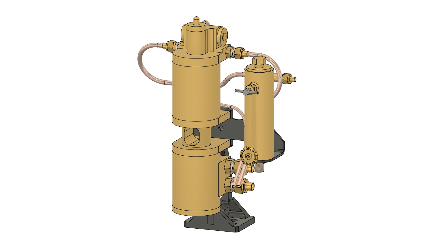
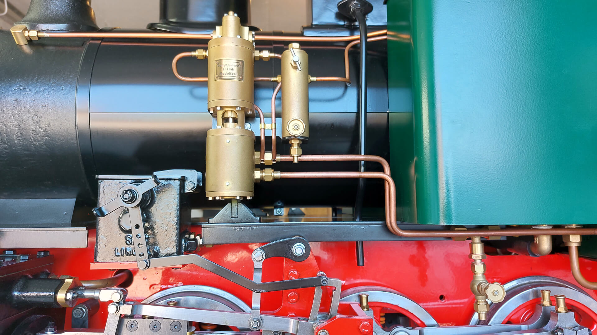
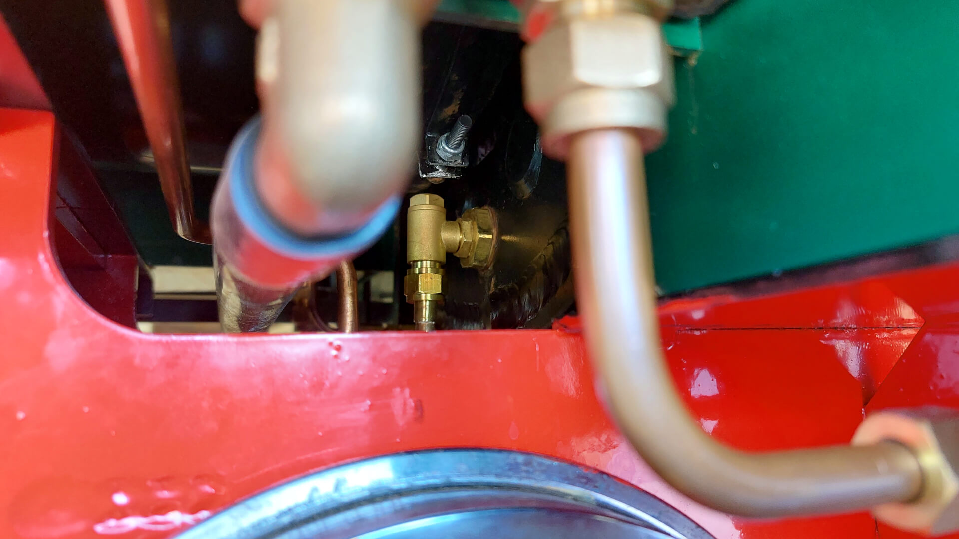
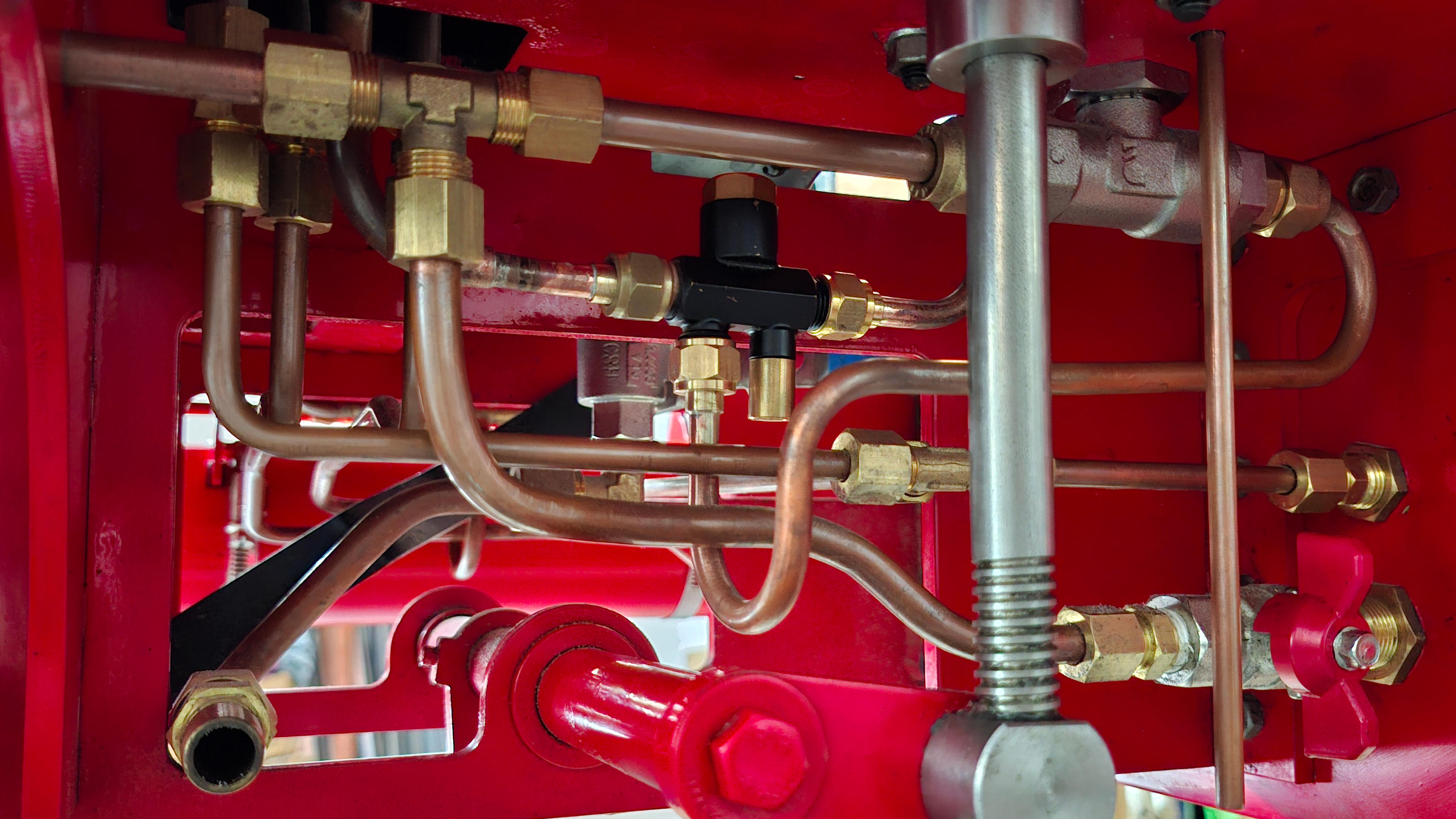
The feed water is injected into the boiler via the opening where the lower control plug is usually situated. I removed the ⅜" plug and replaced it with a ⅛" brass reducing nipple (RN 3818 MS) which takes the check valve. This way I could keep both injectors on the locomotive, and furthermore leave them untouched, so that they would continue to function as usual.
Air Pump
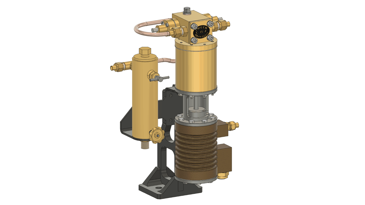
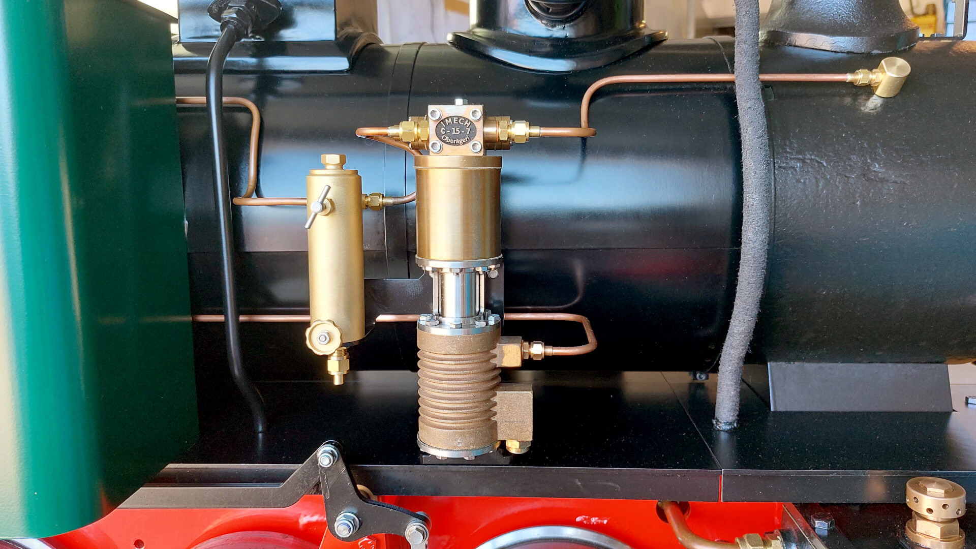
Working pressure 45 to 120 PSI, expected max. air pressure 145 PSI (at 120 PSI steam pressure). In reality, the maximum available air pressure seems to be equal to steam pressure – which works totally fine for my application.
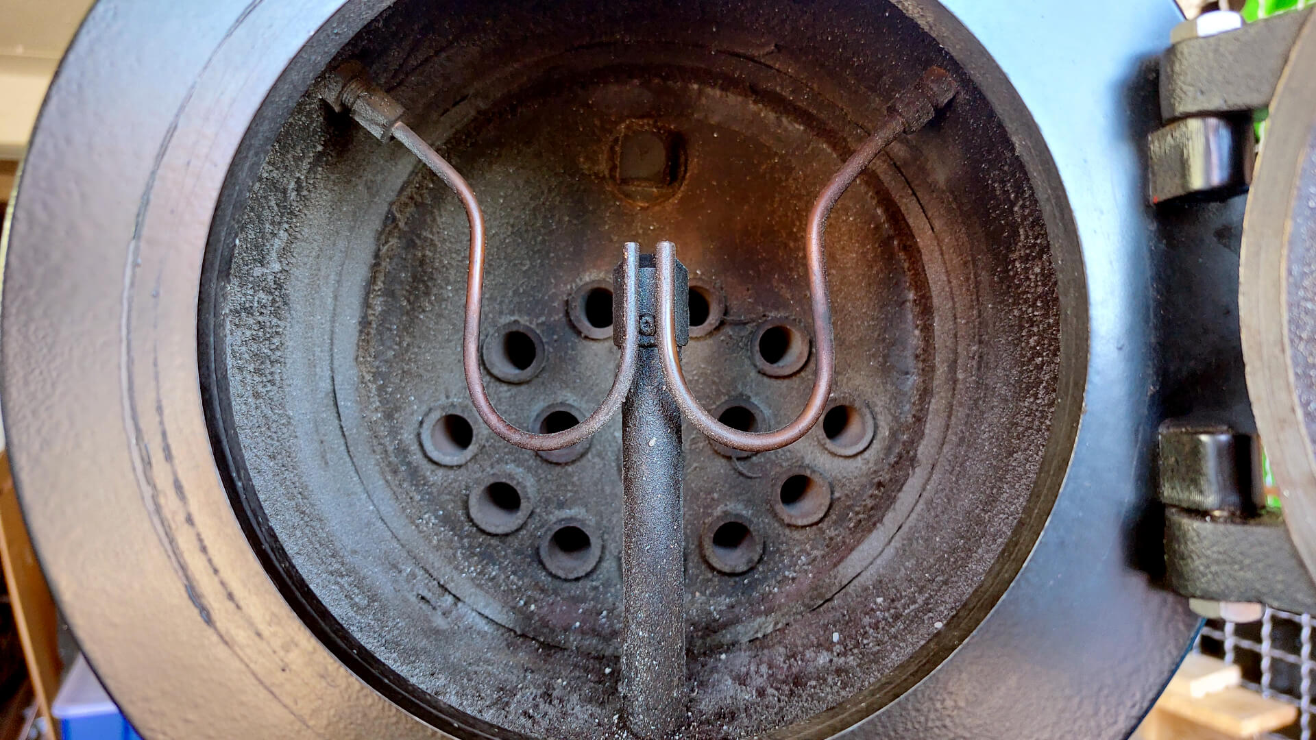
The exhaust steam of the air pump is guided into the smokebox (and up the chimney) via a custom-made metric smokebox fitting .
Valves for the Pumps
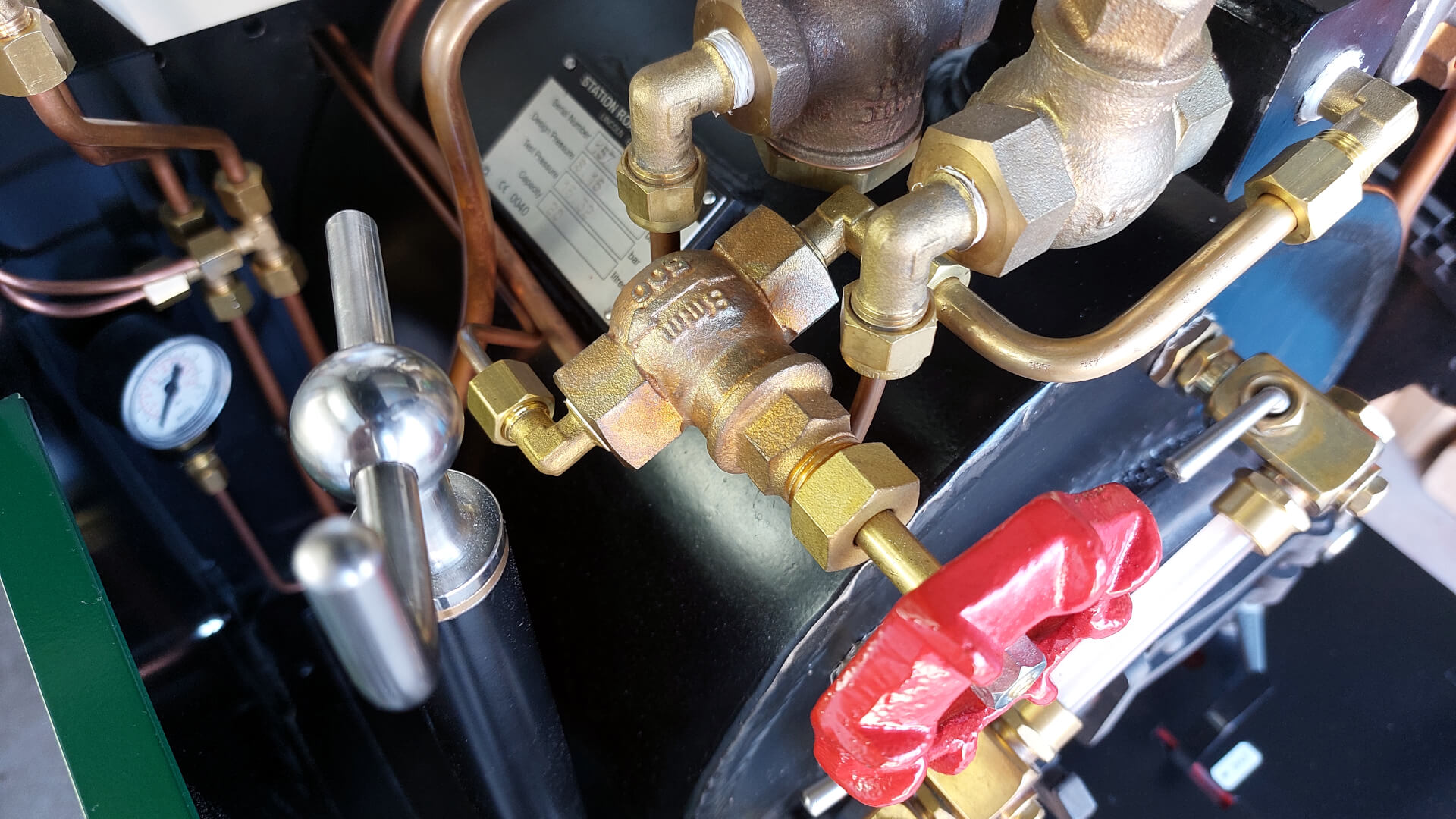
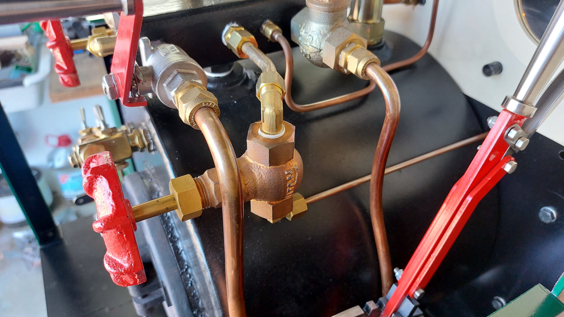
Two extra globe valves to serve the feed and air pump. They seem to be the same ones that Station Road Steam uses, except for the original (bulky) red hand wheels.
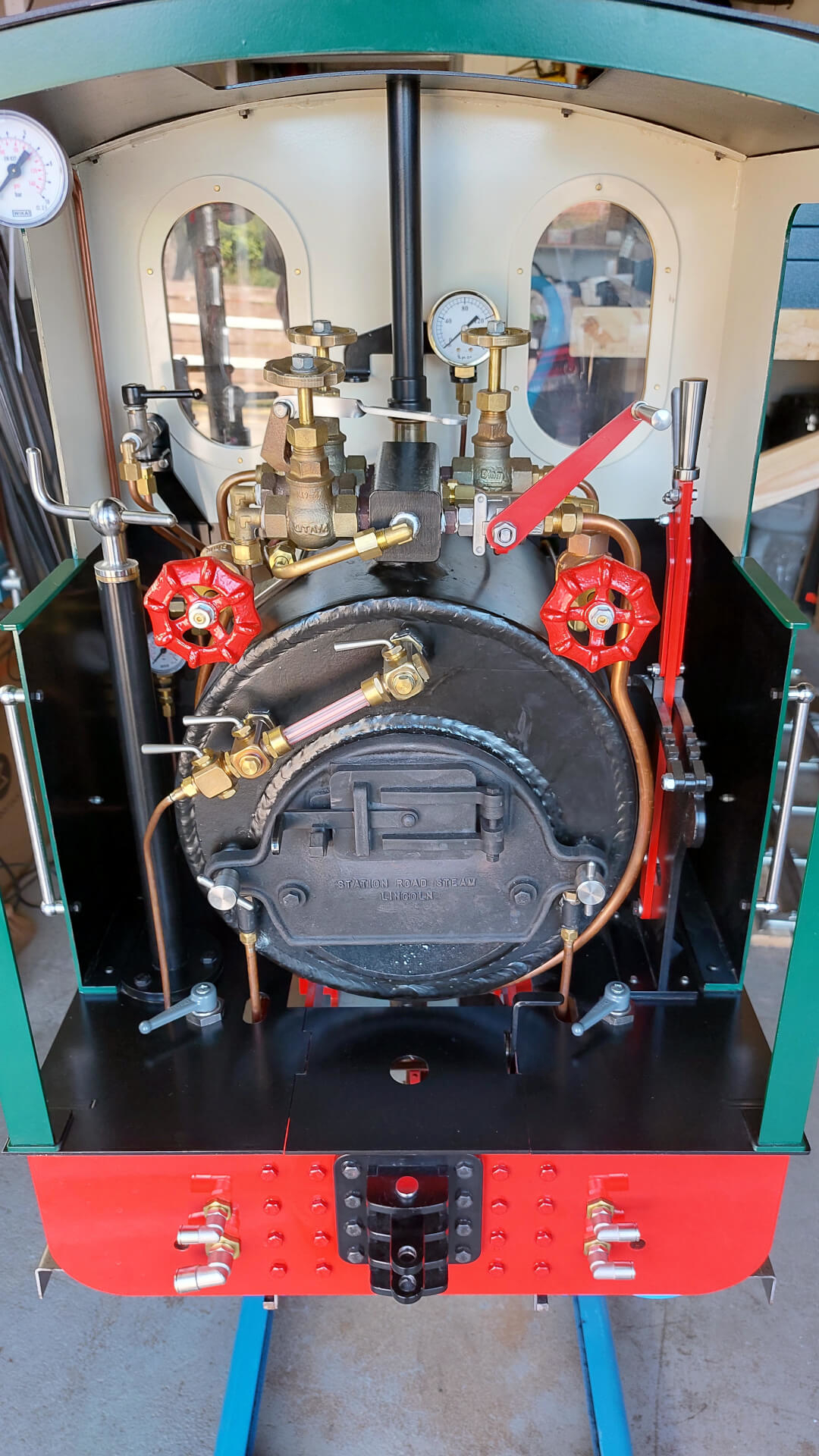
As there was no more room to install them in the same orientation as the existing ones, I had to install them rotated by 90 degrees. I’m very pleased with the result – in my opinion, it makes the cab look even more like a ‘real steam locomotive cab’.
Train Brake System
Driver’s Brake Valve
This valve (parker legris 0482 04 10) allows me to operate a train with air brakes. Main air, brake air, and a silencer for venting the brake line are connected to it.
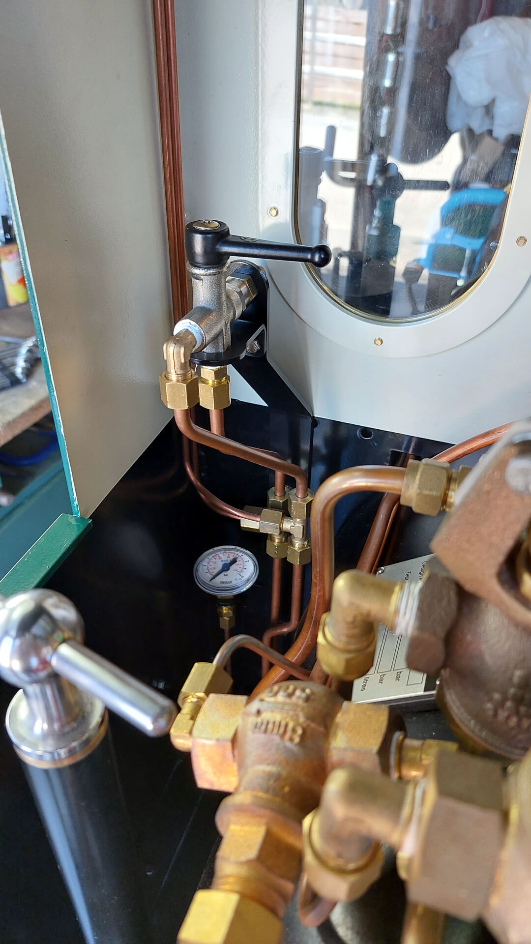
In contrast to the “real” train, this braking system brakes directly, which means that the brake line is filled or emptied directly with the driver’s brake valve. Each braked vehicle carries a small supply tank. In the event of a train separation, they bring the separated train sections to a complete stop. It could be argued that this system is not as safe as it could be – which is indeed the case. At the end of the day it is a balance: Still pretty reliable, and it makes an air-braked system affordable for the hobbyist.
Pressure Gauges
Two pressure gauges to monitor the main pressure (pressurized air) and the brake line pressure. See Pressure Gauge Bracket for more.
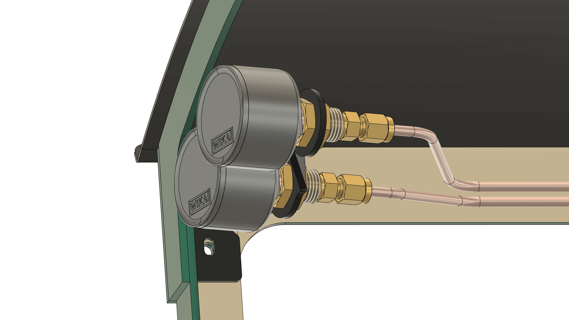
Part List for the Whole Assembly
- 1x Pressure Gauge Bracket (custom)
- 2x G ⅛" Bulkhead Screw Connections (SV 18 MS)
- 2x Pressure Gauges (MW 1040)
- 2x Straight Compression Ring Fittings for 4 mm tubing (KGE 184 KON MS)
- 2x Copper Gaskets (DR 18 CU)
Compressed Air Tank
Made from a disposable oxygen bottle (CFH SF505, unfortunately discontinued and replaced with an aluminium flat-bottom bottle) with a capacity of approximately one litre and a custom laser-cut Air Tank Bracket . The bracket is mounted with the four screws of the reverser stand, which had to be replaced with slightly longer ones. Two stainless steel hose clamps hold the bottle in place.
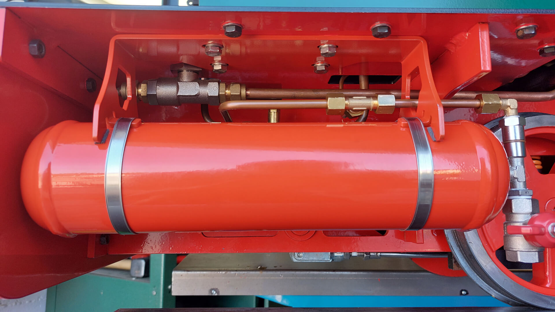
The tank originally has a pretty much useless connection with a left-handed M11x1 outer thread (if I remember correctly). So I got rid of the original connector, enlarged the remaining hole, tapped it for G ¼", and used a matching reducing nipple (RN 1418 MS) to provide a standard G ⅛" connection. This might also be the most fast-forward and space-saving solution compared to creating a special adapter.
Unfortunately, this setup has no real condensation drain – time will tell how this plays out. With my current design I’m hoping that the most condensation will take place in the pipe from the pump to the tank, and thus the condensate will drop off into the valve in front of the tank.
Part List for the Adjacent Tank Periphery
- 1x G ⅛" Reducing Nipple (RN 1418 MS)
- 1x Brass Ball Valve (KH 14 B E-KN)
- 1x T-Fitting (LTE 18 MSV)
- 1x Copper Gasket (DR 18 CU)
- 1x Thread Extension (RN 1818/16 MSV)
- 1x Angled Fitting for 6 mm tubing (KWE 186 MS)
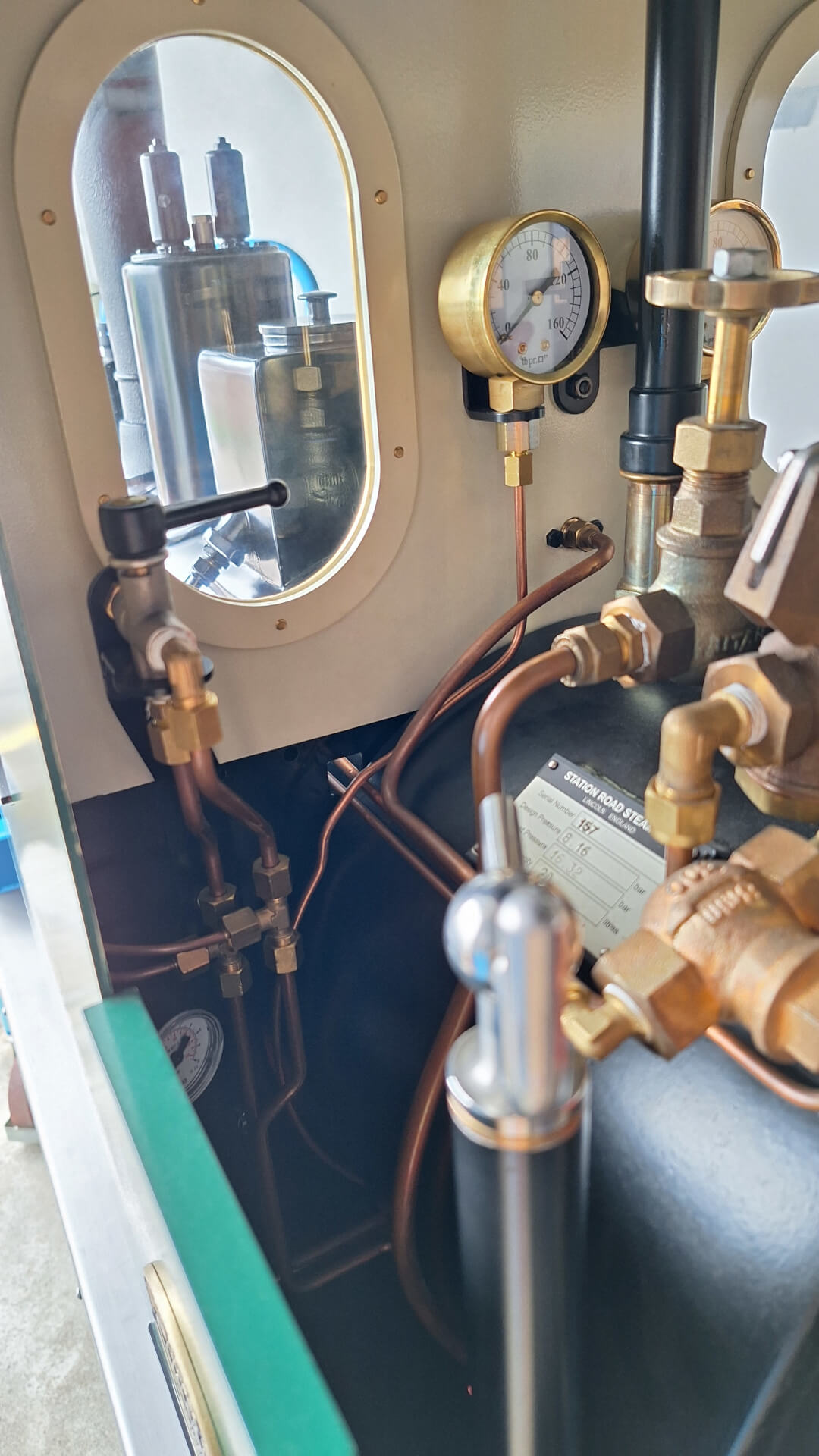
Valve Chest Pressure Gauge
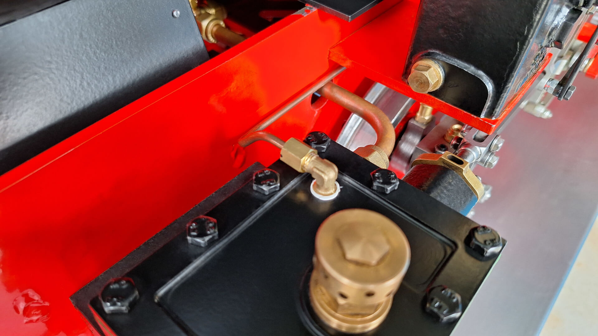
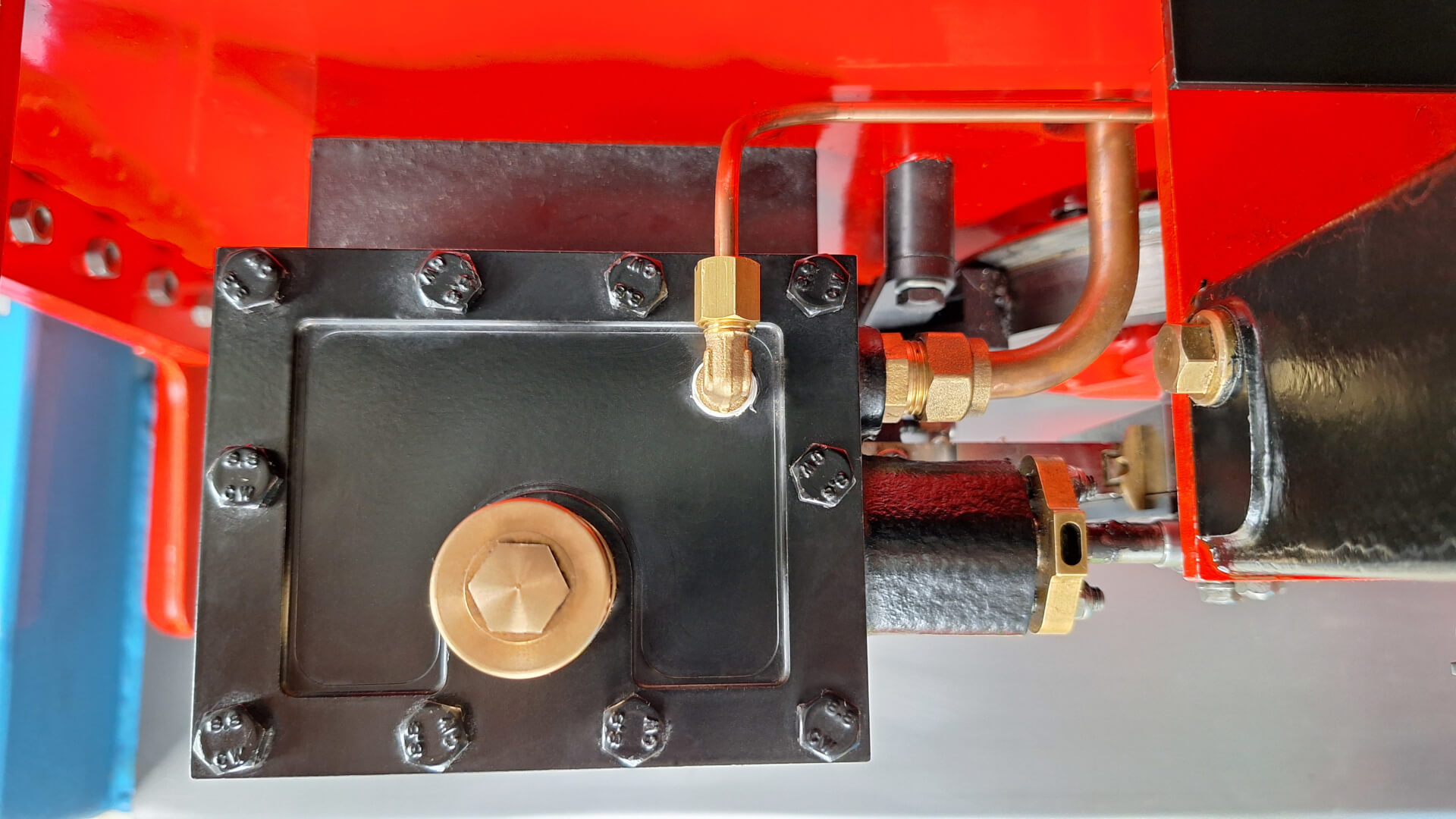
A steam pressure gauge mounted in the cab to monitor the steam pressure directly at the cylinders. The left valve chest is monitored and therefore its cover had to be drilled and tapped to take a ⅛" angled fitting (KWE 184 MS).
Repositioned Blowdown Nozzle
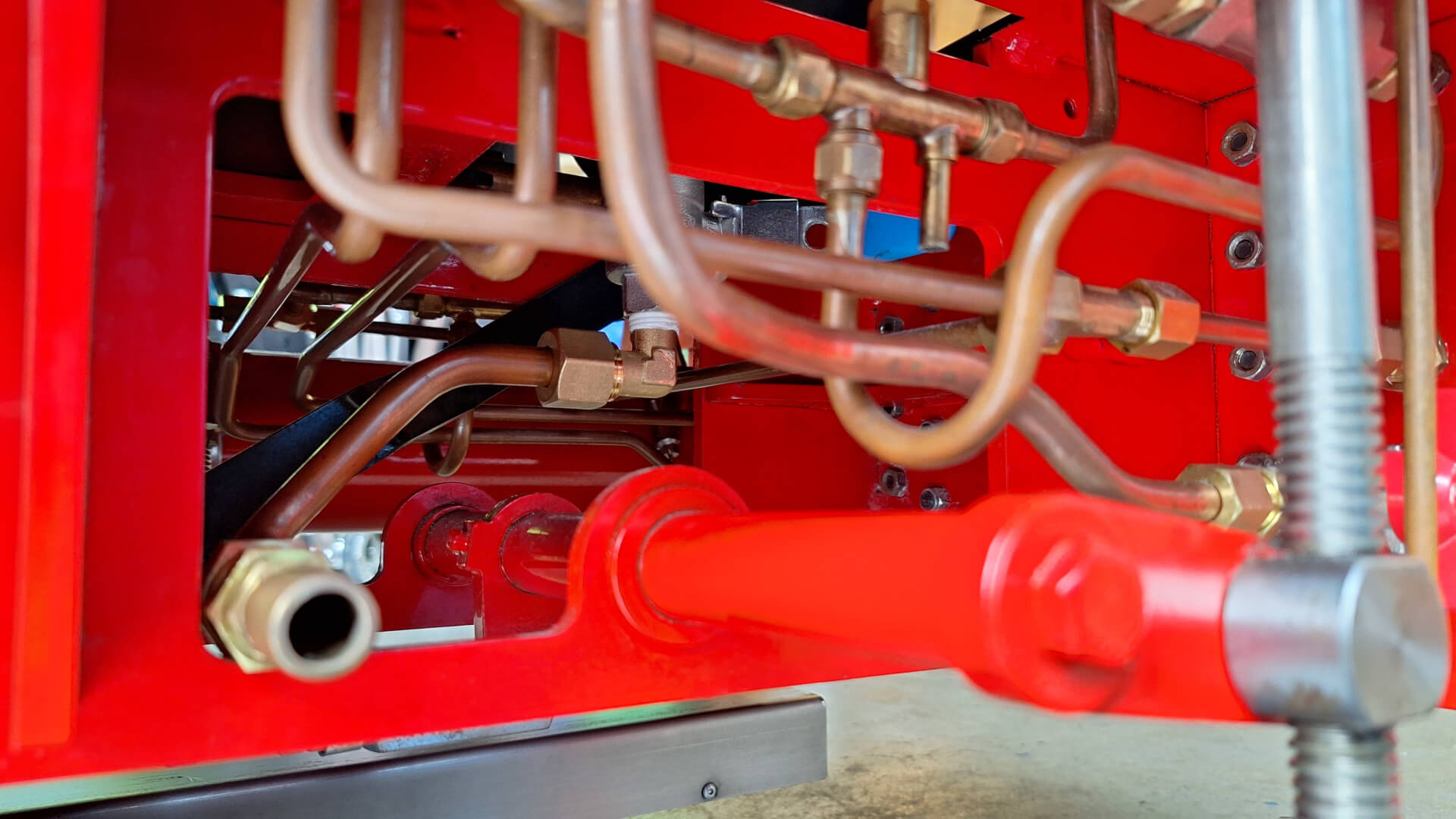
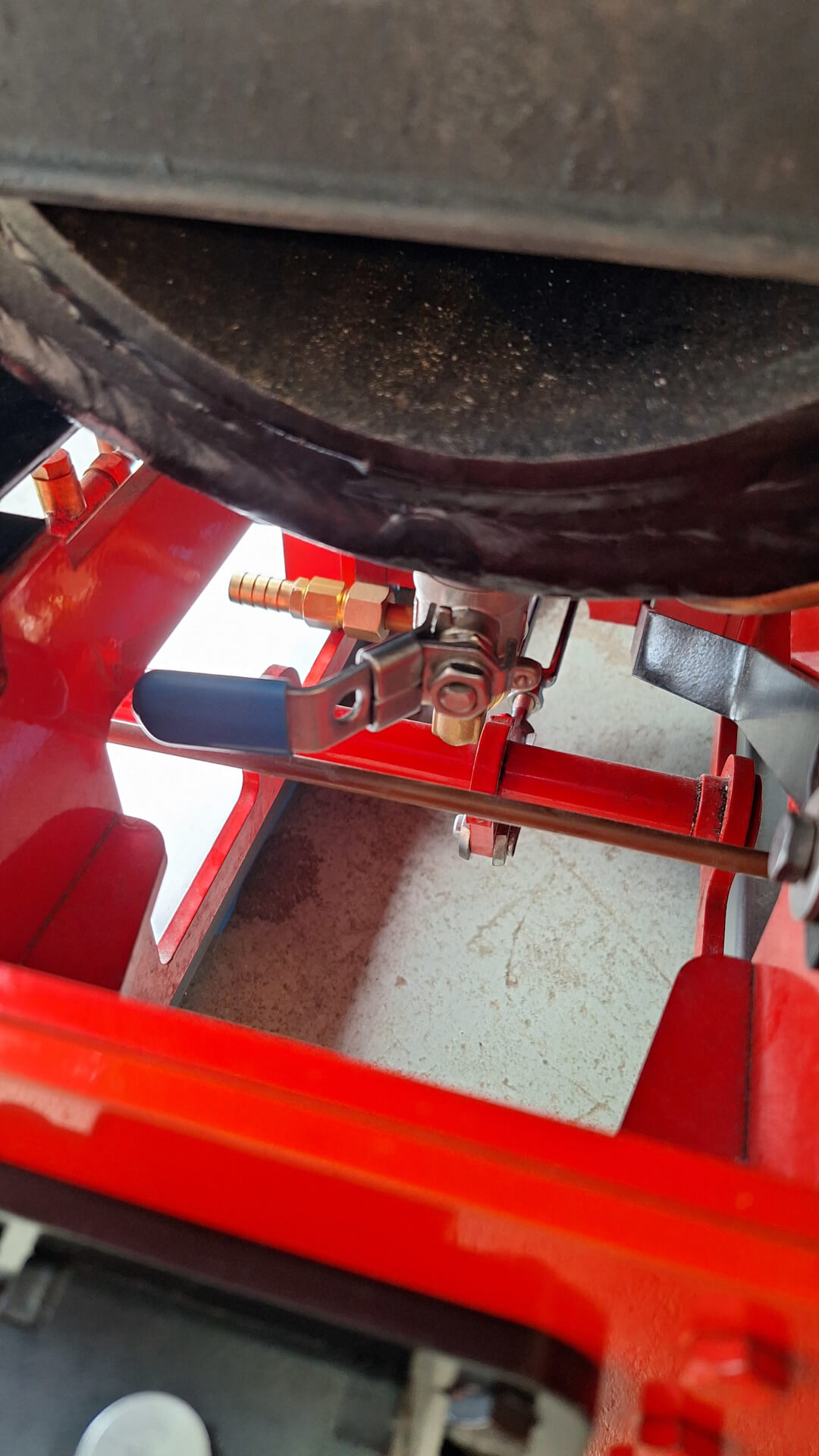
The repositioning of the blowdown nozzle, pointing to the left, grants a more comfortable access for putting the water hose on when filling the boiler with water. It also allows blowing down while running without lifting ballast and dirt up from the track into all the inaccessible crevices and corners of the locomotive frame.
Injector Improvements
Added Ball Valves to the Feed Line
To mitigate the described problems, mainly the “end of day” scenario (see also
Starting an Injector
), I added ball valves (KH18MKESE) into the injector feed
lines, right before the clack valves. Unfortunately, this came with a major drawback: Dynamic resistance. So, to then
counter this, I replaced the injectors’ steam valves. Feeding at 120 PSI becomes a bit of a challenge, now! But I
am in a lucky spot with the mechanical feed pump on warm days – on cold days it still seems working fine with the two
injectors.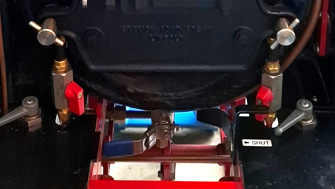
Replaced Injector Steam Valves
To compensate for the now increased feed line resistance, I replaced the injectors’ glob valves with steam-rated ball
valves (KH14KESE – basically the same as the blowdown valve). With their full-diameter bore, they introduce way less
resistance than the globe valves. The handles of the ball valves had to be shortened by about 15 mm to not
interfere with each other. The rubber covers can be removed by just pulling on them. Then shortening the handles and
putting back on the covers is self-explanatory. I also removed the lock tabs to gain free movement of the handles.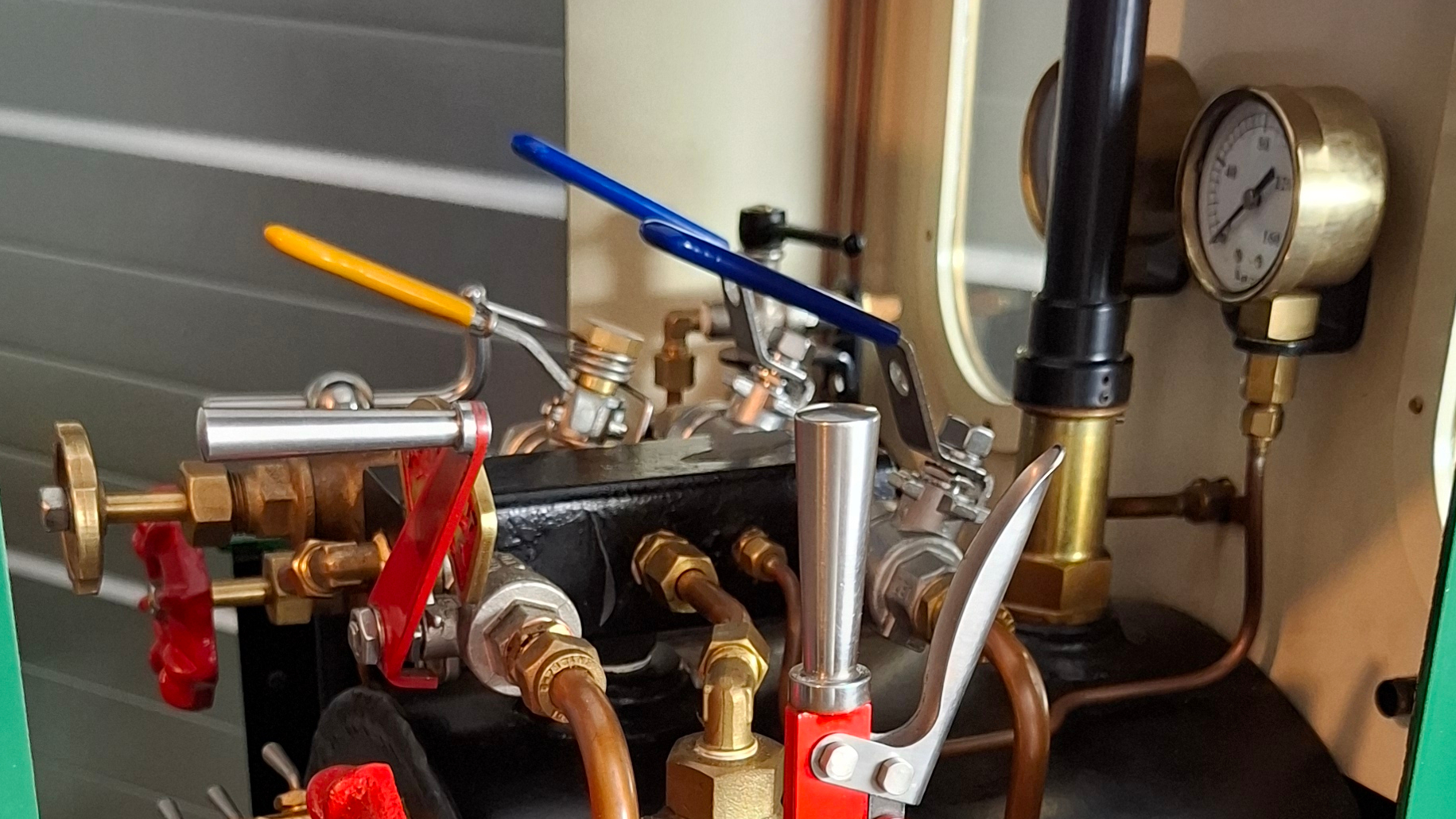
Injector No. 6
And while on it, I decided to replace one of the No. 5 injectors (left-hand side) with the next size “No. 6” from Rex Model Engineers . And what can I say – with this, I got the long-wished “fire and forget” feature: Simply open the water valve fully now, then the steam valve, slowly and all the way, and the injector does its thing without any fiddling with the water valve, anymore.
Extensions & Accessories
Open/Shut Regulator Plate
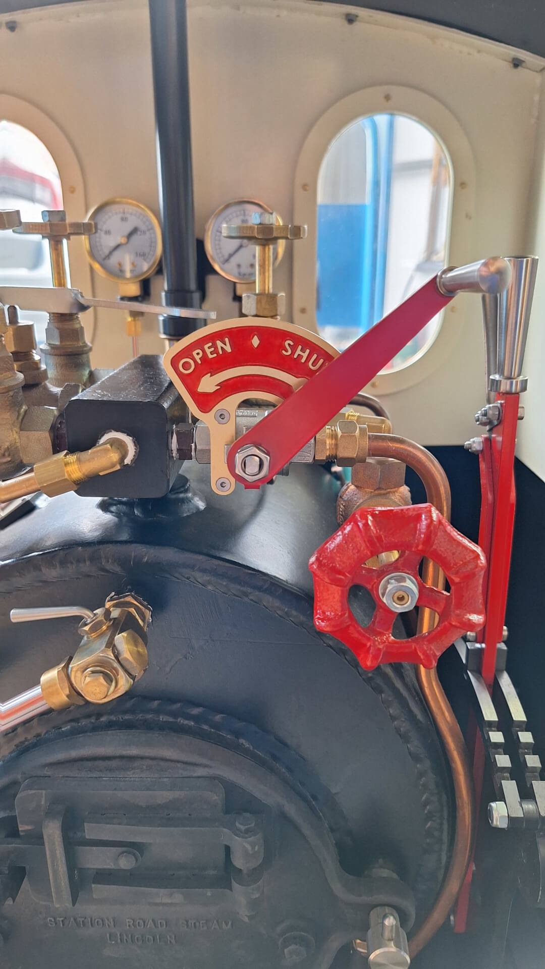
A purely aesthetic feature, mounted on the regulator valve behind the regulator handle, that shows in which direction the regulator is opened or closed. The plate itself is a very fine brass casting and can be acquired from Ride on Railways Ltd . Be advised that they do not explicitly list the plate on their website, but they do have a few more in stock (as of April 2024).
The plate comes pretty much raw; most of the mould material is cleaned off, but some stuff still sticks to the plate, especially in the pointed corners of the letters. A toothpick for the more accessible parts and a needle for the harder-to-reach corners (and the tiny hole of the letter “P”) did the trick for me. I also polished the plate with steel wool before painting because I didn’t want to risk scratching the paint later.
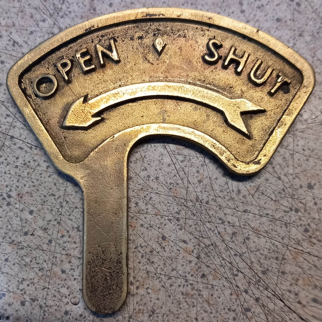
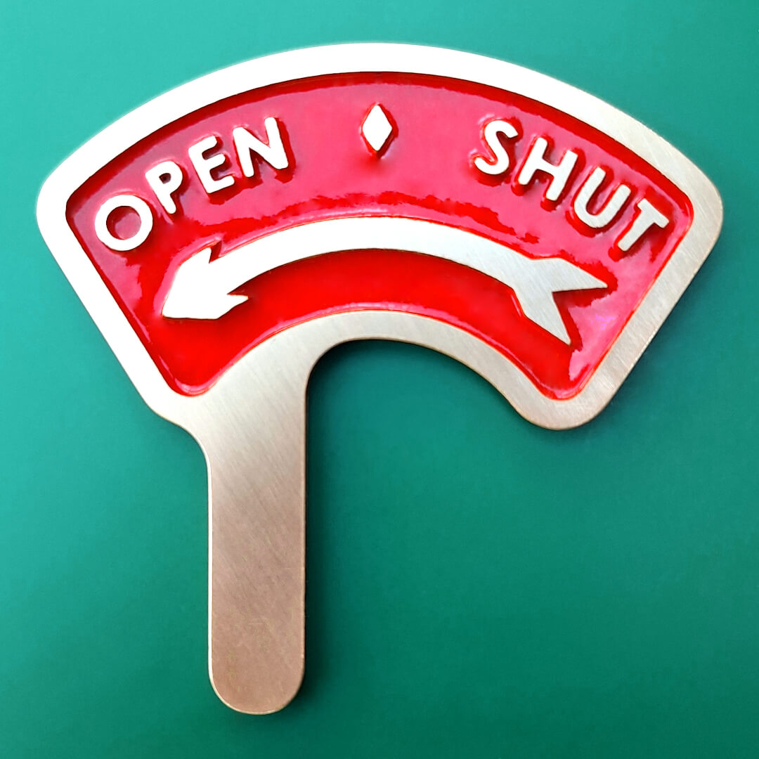
In figure 23, all the dark spots are the remains of the previously mentioned mould material.
After painting with a brush (spraying doesn’t give good coverage in the corners), I sanded the front (face down) on a flat surface with 120, 240, and 600 grit sandpaper to get the finish shown in figure 24.
The plate is mounted with two M3 (x 8 mm) countersunk screws. Before mounting, the holes in the regulator valve had to be drilled and tapped and as you can see in the pictures, the holes in the regulator plate also had to be drilled. I transferred the hole positions from the valve to the plate, drilled them with 3.3 mm, and countersunk at the front.
“Singing” Steam Whistle
Since the Type 28 steam whistle from Station Road Steam does not really “sing” – it is a literal single note with no possibility for variance – I built a “singing” single note bell-type whistle with a base frequency of approximately 860 Hz. The relatively low frequency is against the vibe of original Feldbahns, but chosen due to a personal preference not to “burn” the ears.
Also, the globe-type whistle valve did not allow for enough nuances to the whistle. So I replaced it with a self-closing ball valve, which is far more responsive and allows for more nuanced whistle sounds.
Tender
A self-built air-braked Tender to provide additional water and plenty of coal. But most importantly: the engineer’s seat.
Coupling Adapter
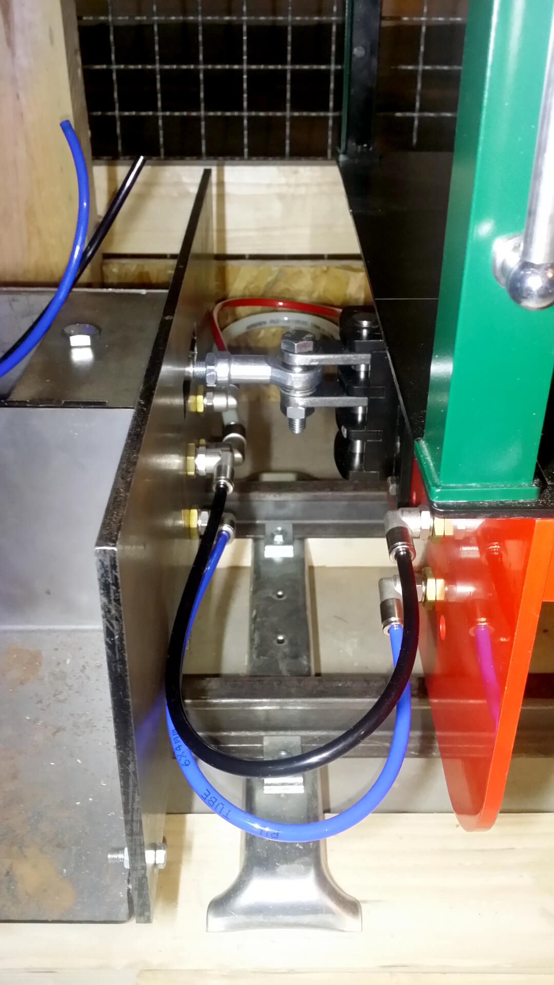
To be able to couple my tender, I had to adjust the coupling height. This unfortunately was necessary, because I had been provided with the dimensions of the older two-slot coupling and I already started constructing the tender while Station Road Steam assembled the ordered Feldbahn.
Lamps
Feldbahn-style lamps to guide through the night – or just for pure aesthetics.